Hacking the Autoterm Air / Planar 2D
As part of my effort to smart up my van, I've looked into how to make my heater controllable with an API. It is a Autoterm Planar 2D (now rebranded as Autoterm Air 2D) diesel heater, and it came with the PU-27 control panel.
Heater and panel are connected with a 4-wired cable. The wires are colored red, blue, white and green. Which made me think: Red and blue is probably the power supply, as that's quite common for car components. And the rest might be RS232? They probably didn't make up their own protocol, because, after all, why should they?
A quick google research led me to Grimoire's Blog, which supported my assumption. Grimoire also dug into the serial protocol used and explains how to build a proxy that sits between panel and heater. Everything received from the panel will be passed on to the heater, and vice versa. If you're interested in that, I suggest you head over to his blog and check it out. For the sake of completeness, I'll repeat the key points here as well:
The wiring is as follows:

- 1: unused
- 2: heater (TX) to panel (RX), 5V, green
- 3: panel (TX) to heater (RX), 5V, white
- 4: ground, blue
- 5: +12V, red
The comm lines are operated at 5V, and using 3.3V signal levels won't work for the heater. So you either need to shift the logic levels (e.g. the TXS0108E should do the trick), or you use some serial to USB converter that can operate on 5V levels out of the box.
Also, all communication is initiated by the panel. The heater responds and never sends messages the panel did not ask for in the first place. After power up, the panel tries a couple of baud settings until it gets a valid response from the heater.
At first I was thinking about building the proxy with my weapon of choice, the ESP8266. But as I'm using a Raspberry Pi in my van anyway, I was fine with attaching two FTDI serial-to-USB converters, just as Grimoire did. That also shortened iteration cycles when I reverse engineered the protocol. Compiling and uploading sketches just takes more time than running some code on my laptop.
The Proxy
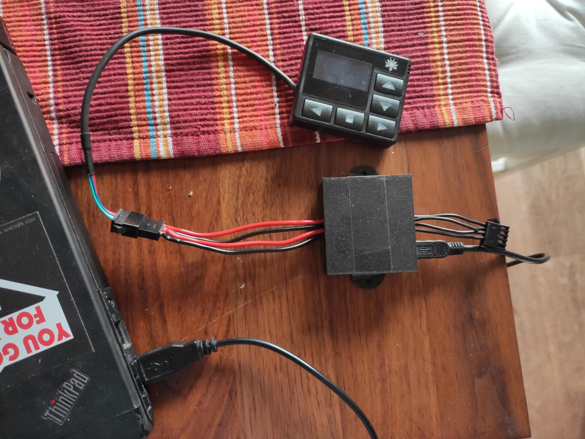
Before being able to analyze the protocol, I needed to build that proxy device that can be plugged between heater and panel. I wanted to be able to restore the original connection in case everything fails, so I've used the same connectors as Autoterm did (5-pin JST SM. Yes, 5 pin.).
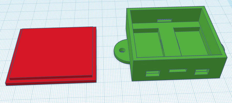
I've also 3d printed a case that holds the two serial-USB adapters, provides space for the necessary wiring and can be wall-mounted next to the Raspberry. Nothing fancy, but does the job.
Print your own if you feel like it: tinkercad stl
Once wired up, I've added some code that passes everything it receives on one serial port to the other, and vice versa. Now I could play with the heater and see which bytes changed.
Protocol
This is what I found out about the protocol. At the end I was able to replicate all functionality of the PU-27.
Basic message structure
The basic message structure is as follows:
0xAA: Preamble. Each sentence starts with this.- Sender
0x03: Message originates from the panel0x04: Response from the heater
- Payload length in bytes
0x00, probably some padding- Command ID, see below
- Payload: Depends on the command or response
- Checksum: CRC16-MODBUS, calculated for the entire message. An online tool for calculating these can be found here: https://www.modbustools.com/modbus_crc16.html
Messages are idempotent, so it does not make a difference if you send a command once or multiple times. In fact, the PU-27 controller usually repeats commands several times.
During regular operation, the panel sends commands in a loop:
0x02: Get settings0x11: Report panel temperature0x0f: Get status0x11: Report panel temperature again
After that, this sequence repeats. Commands are emitted once every ~0.8s.
0x01: Start heater
The payload is organized as follows:
| Offset | Content |
|---|---|
| 0 | 0xFF 0xFF Preamble |
| 2 | Mode, see below |
| 3 | Temperature setpoint in °C as a single byte |
| 4 | Ventilation: 0x01 = On, 0x02 = Off |
| 5 | Power level, 0-9 |
| Mode | Description |
|---|---|
0x01 | By T Heater |
0x02 | By T Panel |
0x03 | By T Air |
0x04 | By Power |
Obviously, the temperature setpoint is only relevant for modes 1-3, and the power level for mode 4.
Example:
Turn on the heater with ventilation and power level 3:
P >> aa 03 06 00 01 ff ff 04 10 01 03 2e af
H << aa 04 06 00 01 ff ff 04 10 01 03 f4 1e
0x02: Get/Set settings
If this command is sent without payload, the heater responds with the current settings. Alternatively, the panel can send new settings. In that case, the payload is identical to the 0x01 (Start) command.
This command is also used to change the settings when the heater is running.
The panel polls the settings periodically.
Example
Set setpoint to 16°C, controlled by heater's sensor, with ventilation.
P >> aa 03 06 00 02 ff ff 01 10 01 03 e2 9c
H << aa 04 06 00 02 ff ff 01 10 01 03 38 2d
0x03: Shutdown
Stops the heater. Stopping the heater can take a while, and you can check the status so see when that's finished.
This sequence seems to be always the same, regardless of the mode used.
Example
C >> aa 03 00 00 03 5d 7c
H << aa 04 00 00 03 29 7d
0x04: Initialization
Sent by the panel when it tries to establish a connection with the heater. Once it receives a valid reply, it sticks to the current connection settings. This command is never used again during regular operation.
Example
C >> aa 03 00 00 04 9f 3d
H << aa 04 05 00 04 10 82 00 15 11 f9 82
0x11: Report panel temperature
This one is used by the controller panel to report the temperature to the heater. This is relevant when the heater is operating in By T Panel mode.
Payload is just one byte (the temperature in °C), and the heater repeats whatever value the panel sends. This command is used during the regular polling cycle, and it is polled twice as often as e.g. the status request.
Example
It's 10°C:
C >> aa 03 01 00 11 0a ba d1
H << aa 04 01 00 11 0a 7a 64
0x0F: Status
The panel polls this one periodically. There is more in this response payload than I figured out, but this is what I know so far:
| Offset | Content |
|---|---|
| 6 | Battery voltage * 10, e.g. 0x84 equals 13.2V |
| 9 | Operating mode, see below |
| 14 and 16 | Ventilation power. During startup this value goes up to 0x96, and then decreases slowly down to 0x46 during regular operation (status 0x04). Also, this value seems to appear twice, god knows, why. |
| Operating Mode | Meaning |
|---|---|
0x00 | Heater off |
0x01 | Starting |
0x04 | Running |
0x05 | Shutting down |
Example
Heater is running, Battery voltage is 13.2V, ventilation is at 109.
P >> aa 03 00 00 0f 58 7c
H << aa 04 13 00 0f 03 00 00 0a 7f 00 84 01 b2 04 00 37 37 00 6d 00 6d 00 64 c3 0a
Implementation
I've written some typescript/node js code that does the interfacing. The software I'm running on the van is a mess to be honest, but I've cleaned up the relevant classes, so you can grab them here.
Some notes on the implementation:
- You can totally inject commands, as long as forward all responses from the heater to the display. That way, the PU-27 is notified about e.g. changed setpoints or heater states. It nicely updates it's views.
- When injecting commands, pretend to be the panel and use it's sender ID. This is fine.
- I've added some code that tracks when the heater state was polled last by the panel. If it's disconnected, a timeout will be triggered and the code takes over polling.
Installation / Deployment
The FT232RL serial-to-usb adapters work pretty much right out of the box on both Windows- and Linux systems. On my Raspberry PI they just popped up as e.g. /dev/ttyUSB0. However, there is no guarantee that one converter will have the same name after a reboot as it did before. So to be sure your setup keeps working you should assign an alias and work with that.
To do so, first check the port names the devices are connected to:
dmesg | grep ttyUSB

[    7.805124] usb 1-1.2: FTDI USB Serial Device converter now attached to ttyUSB0
[    7.813654] usb 1-1.3: FTDI USB Serial Device converter now attached to ttyUSB1
Then check the details for each of the devices found:
udevadm info --name=/dev/ttyUSB0 --attribute-walk
udevadm info --name=/dev/ttyUSB1 --attribute-walk
Armed with that information you can finally set up symlinks by creating a file /etc/udev/rules.d/10-usb-serial.rules. As I'm using identical converters, there is no way to distinguish them other than the USB ports they are attached to. Pick some attributes that describe each converter. I've picked then vendor- and product id, as well as the serial. But that's the same for both devices, so it could just as well be ignored.
My file looks like this:
SUBSYSTEM=="tty", KERNELS=="1-1.3", ATTRS{idVendor}=="0403", ATTRS{idProduct}=="6001", ATTRS{serial}=="A50285BI", SYMLINK+="ttyUSB_panel"
SUBSYSTEM=="tty", KERNELS=="1-1.2", ATTRS{idVendor}=="0403", ATTRS{idProduct}=="6001", ATTRS{serial}=="A50285BI", SYMLINK+="ttyUSB_heater"
KERNELS is the USB port as listed by dmesg, and the other attributes stem from the udevadm command.
After that we have symlinks /dev/ttyUSB_panel and /dev/ttyUSB_heater, which will map to the corresponding devices.
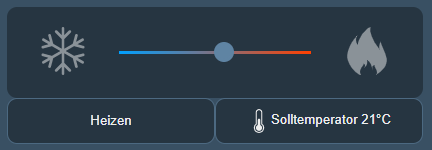
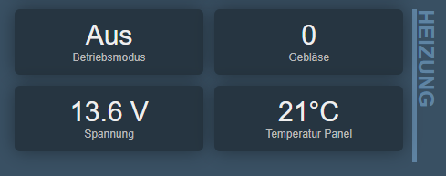
UI
With that information at hand, you should be able to easily integrate the heater into your system. I've built a nice UI for controlling and checking my heater. This is how it looks:
References
Parts
- Raspberry PI 3
- 2x FT232RL USB to serial adapter that supports 5V signal levels
- JST SM 5 pin connectors (1x plug, 1x socket)
- 2x Mini USB patch cables
Links
- Grimoire's Blog. Go read it!
- 3D printed enclosure: tinkercad stl